The Ins & Outs of Industrial Robotic Arms
What Is an Industrial Robotic Arm?
As automated operational equipment deployed in industrial environments, the industrial robotic arm is equipped with three or more programmable motion axes.

It enables the spatial displacement of tooling or workpieces to accomplish manufacturing procedures such as welding, spray painting, palletizing, machine tool loading/unloading and assembly.
1. Differences Between Industrial Robotic Arms and Collaborative Robots
Industrial robotic arms feature fast operation speeds and strong impact force, designed for high speed, heavy payload and continuous mass production. They must be enclosed by safety guard fences to separate humans and machines, making close human-robot collaboration impossible.

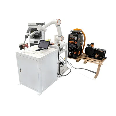
Collaborative robots are equipped with built-in force sensors with highly sensitive collision detection, which will stop immediately when contacting workers. Despite compromised speed and payload capacity, they generally require no safety fences and can work alongside operators at the same workstation.

2. Differences in Performance Parameters
Advantages of industrial robotic arms: high operating speed, heavy payload and long reach, suitable for high-intensity continuous mass production.
Advantages of collaborative robots: lightweight and flexible structure, yet limited in speed and maximum payload, only applicable to processing light and small workpieces.
3. Applicable Production Scenarios
Industrial robotic arms: high-cycle and heavy-load processes including welding, palletizing of heavy materials, stamping, and machine tending.
Collaborative robots: small-parts assembly, inspection, polishing, light handling, and flexible manufacturing with small batches and diverse product types.
How Does an Industrial Robotic Arm Work?
Industrial robotic arms feature a serial link structure. A rigid base is firmly mounted on the ground, with multiple mechanical links and rotary joints connected end-to-end, extending all the way to the wrist and the end tool flange. The vast majority of robotic arms on the market adopt this serial design; a small number of parallel robots exist but have limited applicable scenarios, which will be elaborated on later. Each joint corresponds to one independently controllable motion axis, and standard models are equipped with six axes labeled J1 to J6.

The six axes fall into two groups: The first three axes J1 (base), J2 (shoulder) and J3 (elbow) are positioning axes. J1 rotates the entire arm left and right, J2 swings the lower arm forward and backward, and J3 lifts and lowers the upper arm. Working in tandem, they can move the wrist to any position within the working envelope.
The other three axes J4, J5 and J6 are integrated inside the wrist as orientation axes. They can roll, tilt and twist the end tool to align it with workpieces from any angle.
Simply put: three axes determine the tool's position, while the other three adjust its posture. Six axes represent the minimum configuration required to position and orient a tool freely at any point and any angle in space, which is why six-axis robotic arms are the mainstream solution for factory automation.
How to Read a Robot Arm Datasheet
After narrowing down model categories such as six-axis robotic arms, collaborative robots and palletizing robots, specification sheets serve as the core reference for evaluating the practicality of each model. The nominal parameters provided by manufacturers are mostly optimal values obtained under ideal operating conditions, which often conceal critical operational limitations and can easily lead to incorrect model selection.
Five core parameters directly determine the operational performance of robotic arms: rated payload, working radius, repeat positioning accuracy, cycle time, and degrees of freedom (number of axes). Notably, payload and working radius are mutually restrictive; a comprehensive overall assessment is required instead of evaluating any single parameter in isolation.
1. Payload
when operating at rated speed with standard reach, without performance degradation or service life loss.Key Pitfalls to Avoid During Model Selection
Do not only calcuIt refers to the maximum load weight that a robotic arm can stably carry late the weight of the workpiece itself; the total weight of the End-of-Arm Tooling (EOAT) must be added, including accessories such as grippers, vacuum suction cups, quick-change devices, sensors and cables.
Two Core Criteria
The rated payload is defined based on the standard load center of gravity and mounting offset distance. Heavier tooling or shifted center of gravity will reduce the actual load capacity. Always check the payload-reach curve instead of relying solely on the advertised nominal payload value.
A safety margin of 20% to 30% must be reserved during model selection to counteract inertia during acceleration and deceleration and accommodate future tooling upgrades. A payload that only just meets the working requirements indicates an undersized specification.

2. Maximum Reach
It means the maximum straight-line distance from the center of the robotic arm base to the tool flange, which determines the effective working envelope. Its working area is not a regular sphere; blind zones exist above and below the base, and joint mobility is extremely poor in areas close to the base.
Model Selection Guidelines
Do not select a model solely based on maximum reach. Verify the working envelope against pick-and-place positions, tooling layout, and material inlet/outlet points. End tooling can extend the working radius, yet joint rotation angles will shrink the effective operating range. Longer reach corresponds to lower payload capacity and larger floor footprint of the unit, as these parameters restrict one another.
3. Repeat Positioning Accuracy vs Absolute Positioning Accuracy
Repeat Positioning Accuracy
Consistency of a robotic arm returning repeatedly to manually taught target points, typically ±0.0X mm. It is a key promotional parameter highlighted by manufacturers and suitable for most operation scenarios with fixed motion trajectories.
Absolute Positioning Accuracy
Precision of a robotic arm reaching untaught coordinates generated from CAD drawings, offline programming software or vision systems. This accuracy value is far inferior to repeat positioning accuracy and rarely listed in product specifications. It serves as a critical core parameter for offline programming, vision integration and robot interchangeability applications.
Common Misconception
The two metrics are not interchangeable. High repeat positioning accuracy does not guarantee high absolute positioning accuracy.
4. Cycle Time / Operating Speed
This parameter reflects the theoretical production capacity of equipment and represents the most idealized index in product specifications. The rated cycle time and maximum speed published by manufacturers are calculated under standard operating conditions featuring short travel distances, light payloads and optimized parameters, which cannot match real-world production environments.
Actual cycle time is affected by payload weight, travel distance, intermediate waypoints, and process dwell time (for dispensing, welding, precision alignment buffering). Real production output is generally lower than the rated value. Measured test data or simulation results shall prevail for core production scenarios.
5. Degrees of Freedom (DOF) / Number of Axes
It refers to the number of independently movable joints on a robotic arm, which determines the flexibility of the end effector's working posture:
1. 4-axis robots (SCARA robots, most palletizing robots): High speed and rigidity, with end effectors only capable of vertical operations. Ideal for planar pick-and-place, palletizing and simple assembly tasks.
2. 6-axis robotic arms: Adjustable postures at all angles, enabling inclined docking with workpieces. Suitable for welding, complex assembly, and machine loading/unloading of irregularly shaped workpieces.
3. 7-axis redundant robotic arms: Capable of avoiding equipment obstacles while maintaining stable end-effector postures even in compact workstations, suited for complex space-restricted working conditions.
Selection Principle: Configure axes according to actual demand. High-spec multi-axis models are unnecessary for simple planar applications to avoid unnecessary cost expenditure.
Application Scenarios
Specification sheets are only meaningful when aligned with actual production processes. A repeatability of ±0.05 mm, a critical metric for welding, bears no relevance to 400-ton stamping lines, where motion timing and floor footprint take precedence.
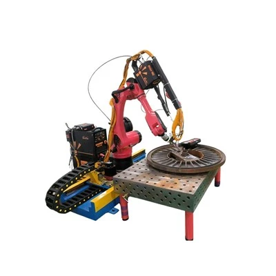
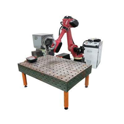
1. Welding: Select Robots Based on Weld Path Instead of Payload
Arc welding relies heavily on precise path tracking. Weld seams are often curved, vertical, or recessed deep inside fixtures. The welding torch must maintain a consistent standoff distance and travel angle, as the molten weld pool is highly susceptible to tiny deviations. Torches and their cables weigh merely a few kilograms, so payload is not a top priority. Key requirements include high continuous path accuracy, a slim and agile wrist, and ample working reach. The recommended solution is a 6-axis articulated robot with a 6–20 kg payload, equipped with seam tracking or through-arc sensing systems and a controller enabling smooth motion interpolation.
2. Painting & Adhesive Dispensing: Prioritize Uniform Coating Over Spraying Speed
Two mandatory standards apply to painting robots: full explosion-proof construction and consistent coating thickness. Paint booths contain flammable solvent mist, making standard robotic arms a severe fire hazard. The spray gun must maintain constant distance, angle and travel speed; inconsistent movement leads to common defects such as sagging, bare patches and orange peel texture. Hollow through-arm wrists internally route paint and air hoses to avoid pipe interference with the spray pattern. Lightweight, long-reach explosion-proof 6-axis robots are ideal, featuring full IP protection against overspray and optimized for stable trajectories rather than heavy payload handling.
3. Palletizing & Depalletizing: Select Robots by Payload, Reach and Cycle Time
High precision is unnecessary for palletizing. Model selection hinges on three factors: payload, working radius and cycle speed. Standard cartons weigh 15–50 kg, and robots must cover the full stacking area of pallets. A pallet stacked 2 meters high requires roughly 3 meters of reach, with output measured in cartons per minute. 4-axis palletizing robots deliver optimal performance. Their dedicated vertical wrists eliminate redundant axes, channelling all motor power into load capacity and wide reach for superior cost efficiency.
To see whether we fit, put a real requirement in front of an engineer. Send your part drawing, cycle time, and cell constraints, and we'll come back with a configuration and a lead time - [Request a quote] / [Talk to an engineer] or message us on WhatsApp. More on who we are on our [About page], and recent builds under [Case studies].